|
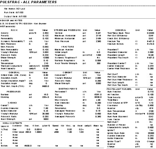
Stimulation Design Considerations Based on the results of Marathon in the Big Horn Basin with stimulation in combination with the gel treatments, it should also be included in the Teapot Tensleep design. Since this treatment is for sandstone, the acid frac is not considered appropriate. The EOB perforating is considerably more expensive than the propellant stimulation. Therefore, the propellant stimulation is the recommended approach. The challenge is to get stimulation over 123 gross feet of perforated interval. There are two major service companies currently providing propellant stimulation treatments. These are ServoDynamics' Stress Frac and Owen Oil Tools' Stim Tube. The Stim Tube is offered through Baker Atlas and Halliburton. One important difference between the old propellant technology, and the new technologies is the realization that explosion speed, or order, determines the nature of the damage (or stimulation). A high order explosion such as nitroglycerine, leaves rubble. This tends to continue to disintegrate and come into the wellbore through time. It also is damaging to the wellbore equipment. A lower order detonation is a bit slower, and can dissipate energy further into the formation. It is still fast enough so that it does not react to the insitu stress field. It then causes a sphere of cracks around the perforations without damaging wellbore equipment. An even lower order detonation gives results equivalent to a hydraulic fracture, where the energy is expended slowly enough to find the direction of maximum principle stress and align with it. It is very important to design the stimulation with the rock mechanics and wellbore geometry in mind. This requires a special computer simulation, which has been history matched to previous stimulations and can model the energy release from the propellant and the expenditure of the released energy into the wellbore and rock. The right combination of explosive charge and wellbore conditions can be determined to give the correct order detonation and create the desired radial fracture pattern. Results of this simulation are presented below: U.S. Department of Energy well: 76 TPX 10 Tensleep ss Table 3. Simulation input and output data
|
